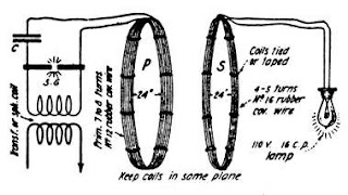
wireless electricity transmission working and its circuit diagram
 in the present day, electricity is treated as one ao the basic requirements of human beings. but, the cost of making electricity is high. according to the energy information records, approximately 50% of all electricity plants are contaminating coal plants. various changes in the environment have happened over the last thirty years, which are injurious to the forthcoming of this planet. to overcome this, here is a solution to diminish greenhouse gas emissions into the soil's atmosphere through are alternative power generation. one sustainable technology leading this change is wireless electric power transmission or inductive power transfer.
wireless power transmission
the basic wireless power transmission includes the inductive energy that can be transmitted from a transmitter coil to a receiver coil through an oscillating magnetic field. the dc current supplied by a power source is changed into high-frequency AC current by particularly designed electronics built into the transmitter.
in the transmitter section, the AC current increases a copper wire, which creates a magnetic field. once a receiver coil is located near to the magnetic field, then the magnetic field can induce an AC current in the receiving coil. rectifier and filter in the receiving side converted the AC signal to DC, which becomes working power.
Wireless power Transfer circuit

The simple wireless power transmission circuit is shown below. the required component of this circuit mainly includes 20-36 SWG copper wire, one battery or DC supply, transistor BC547 / 2N2222, and LED.
Transmitter
Take a PVC pipe a wrap wire on it up to 15 turns and make a lop of the center terminal and continue the process next 15 turns (15 - loop - 15). now take a transistor cod to connect its base terminal to one end of the copper coil, the collector terminal to the other end of the copper coil, and now connect the emitter terminal to the -ve terminal of a battery. the center terminal of the copper coil will be connected with the +ve terminal of the battery. when the receiver coil is placed 5cm above the transmitter coil, then the LED will be glow.
if you have any doubt regarding this circuit please watch this video
circuit working
The wireless energy transmission can be defined as the energy that can be transmitted from the transmitter to a receiver through an oscillating magnetic field.
to accomplish this, power source (DC current) is changed into high-frequency AC(Alternating Current) by particular designed electronic erected into the transmitter. The AC boosts copper wire coil in the transmitter, which produces a magnetic field. when the receiver coil is placed in proximity of the magnetic field, the magnetic field can make an alternating current AC in the receiving coil, rectifier and filter in the receiving device converted AC to DC


Sir please make a video on how to make power bank module.
ReplyDelete